On Ecampus under the
"Submit Homework" menu option, submit a jpg or png image of your logic circuit
and the .cpp source code file for your program.
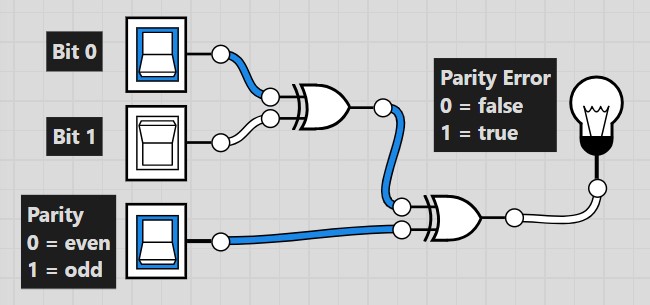
1. In data communications, parity is sometimes used to detect
transmission errors. Assume for each byte transmitted, an extra
parity bit is transmitted that is set to whether the byte has and even
or odd number of 1's. Using even parity, if the number of 1's is
even, then the parity bit is set to 0. If the number of 1's is
odd, then the parity bit is set to 1.
|
If the parity bit does
not match the number of 1's in the byte, then there is an error.
|
Use logic.ly to create a working circuit that outputs true (1) or false (0) on whether a byte (8 bits) matches its parity bit. Label the inputs and outputs appropriately. Below is an example circuit with a 2-bit input.
2. Write a console C++ program (compilable
with GCC) that converts a
decimal number from 0-255 to binary and hexadecimal. Let the user know if
the number they entered is out of range. <iostream> is the
only library you can include. Add leading zeroes so the binary answer has 8 bits.
You must follow the algorithm shown in my tutorial video.
Example output
This program converts
an integer to binary and hex.
Enter an integer: 205
Binary: 11001101
Hex: CD
Enter an integer: 14
Binary: 00001110
Hex: 0E