< Prev
Next >
Chapter 2 -
CPU Instruction Cycle
2.1 CPU Instruction Cycle Wiki
Most computers follow the von Neumann architecture which consists of a CPU (including Control Unit and Arithmetic Logic Unit), memory, mass storage, input, and output. The instruction cycle (also known as the fetch-decode-execute cycle) is the basic operation process of a CPU in a von Neumann architecture computer.
|
CPU Components used in the Instruction Cycle |
||
| Component | Abbreviation | Function |
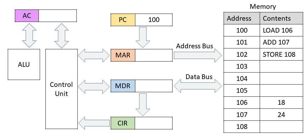
| Program Counter | PC | A register that stores the memory address of the instruction that is next to execute. It is incremented for every instruction. |
| Memory Address Register | MAR | Holds the address of the memory to read or write |
| Memory Data Register | MDR | Holds data fetched from memory or data waiting to be stored in memory |
| Current Instruction Register | CIR | Holds the instruction that is fetched from memory |
| Accumulator | AC | A register that holds intermediate ALU results |
| Control Unit | CU | Decodes and coordinates executing the instruction in the IR |
| Arithmetic Logic Unit | ALU | Performs mathematical and logical operations |
|
CPU Instruction Cycle Steps |
|
| Step | Description |
| Fetch | The next instruction located at the PC address is fetched and loaded into the IR. Afterwards, the PC is incremented to point to the next instruction. |
| Decode | The CU determines what operands are needed and stores them in the appropriate registers. |
| Execute | The CU executes the instruction. The ALU is used for logic or arithmetic. |
The simplified animation below allows you to step through the instruction cycle steps and see how the different components work together. On the right is a block of memory that contains both instructions (100 - 102) and data (106 - 107). These three instructions add 18 and 24 then stores the result into address 108.
 |
|||||
|
|
< Prev |
Next > |
Step 1/22: PC (Program Counter) loaded with address of first instruction | ||
2.2 Microcode
CPU machine language instructions can be
implemented directly in the control unit (hardwired) or by small programs stored
permanently in the CPU called microcode. Microcode are programs that
translate complex machine language instructions into simpler steps. You
can also think of microcode as programs for the logic gates. Microcode
will allow simple architecture CPU's to emulate more powerful architectures with
wider word length. Often, simple machine language instructions are
hardwired and more advanced ones that require a series of steps are microcoded.
2.3
Interrupts
Interrupts alter the normal flow of
instruction execution.
Hardware Interrupts are used by devices when they require attention from
the Operating System. These include keyboard and mouse input. The act of
initiating a hardware interrupt is called an interrupt request (IRQ). A
Programmable Interrupt Controller (PIC) receives the IRQ's and sends them to the
CPU. The IRQ is followed by a number designating what devices requested
it. In older x86 systems, IRQ numbers might need to be manually configured
so that hardware devices don't conflict with each other. In newer x86
systems, an Advanced Programmable Interrupt Controller (APIC) is used which adds
support for multi-core CPU's.
When a hardware interrupt occurs, the CPU will push the registers for the
current program onto the stack. The code for the interrupt is loaded and
executed. After it's finished, the stack is popped and the original
program continues.
Software Interrupts are created by the CPU itself. A divide-by-zero will throw an interrupt that will be caught by the Operating System which decides what to do. C++ and Java have the try/catch instruction that interrupts normal execution.
2.4 Instruction Pipelining
Pipelining attempts to keep every bit of the CPU busy by overlapping instructions. Typically, each part of an instruction takes one clock cycle. There are limitations to pipelining since many instructions will depend on the results of the previous instruction. Below is a basic 5-Stage Pipeline.
|
5-Stage Pipeline |
|||||||
| Clock Cycle 1 | Clock Cycle 2 | Clock Cycle 3 | Clock Cycle 4 | Clock Cycle 5 | Clock Cycle 6 | Clock Cycle 7 | |
| Instruction 1 |
Fetch |
Decode |
Execute |
Memory Access |
Writeback |
||
| Instruction 2 |
Fetch |
Decode |
Execute |
Memory Access |
Writeback |
||
| Instruction 3 |
Fetch |
Decode |
Execute |
Memory Access |
Writeback |
||
| Instruction 4 |
Fetch |
Decode |
Execute |
Memory Access | |||
| Instruction 5 |
Fetch |
Decode |
Execute |
||||
2.5
CISC
versus RISC
A complex instruction set computer (CISC)
is a CPU that handles advanced operations. The larger instruction set
allows the programmer to use more complex instructions therefore taking fewer
lines of assembly code. The complex instructions may take multiple clock
cycles to execute. The x86 CPU's are CISC.
A reduced instruction set computer (RISC) is a CPU that uses simpler
instructions that take just one clock cycle. RISC CPU's are less
complicated with the instructions being more optimized. They typically
have more registers meaning less memory reads and writes. Pipelining is
also more optimized on RISC. RISC is used in some mainframe CPU's along
with Apple and Android smart phone CPU's.