Chapter 1 - Logic Gates
1.1
Logic Gates
Logic gates are the building blocks used in
designing a CPU.
In a microchip, a logic is made up of a specific arrangement of transistors
created on a silicon wafer.
Each terminal of a logic gate is either in high state
(binary 1) with +5 volts or low state (binary 0) with no voltage. Below
are some of the basic logic gates.
| Type |
Shape |
Truth
Table |
| NOT |
 |
|
| AND |
 |
|
Input A |
Input B |
Output |
| 0 |
0 |
0 |
| 0 |
1 |
0 |
| 1 |
0 |
0 |
| 1 |
1 |
1 |
|
| NAND |
 |
|
Input A |
Input B |
Output |
| 0 |
0 |
1 |
| 0 |
1 |
1 |
| 1 |
0 |
1 |
| 1 |
1 |
0 |
|
|
| Type |
Shape |
Truth
Table |
| OR |
 |
|
Input A |
Input B |
Output |
| 0 |
0 |
0 |
| 0 |
1 |
1 |
| 1 |
0 |
1 |
| 1 |
1 |
1 |
|
| NOR |
 |
|
Input A |
Input B |
Output |
| 0 |
0 |
1 |
| 0 |
1 |
0 |
| 1 |
0 |
0 |
| 1 |
1 |
0 |
|
| XOR |
 |
|
Input A |
Input B |
Output |
| 0 |
0 |
0 |
| 0 |
1 |
1 |
| 1 |
0 |
1 |
| 1 |
1 |
0 |
|
|
1.1
Combinational Circuits
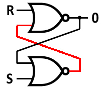
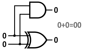
Logic gates are combined to create the
circuitry in microchips. The SR Latch below can function as one bit of
memory - it stores a 1 when you press set (S) and 0 when you press reset (R). The 2 Bit Half Adder adds two binary digits.
|
SR Latch |
| |
Click |
 |
| |
|
| |
|
| |
|
| |
Click |
|
|
Half Adder |
|
|
 |
|
|
|
|
|
Click |
|
Click |
|
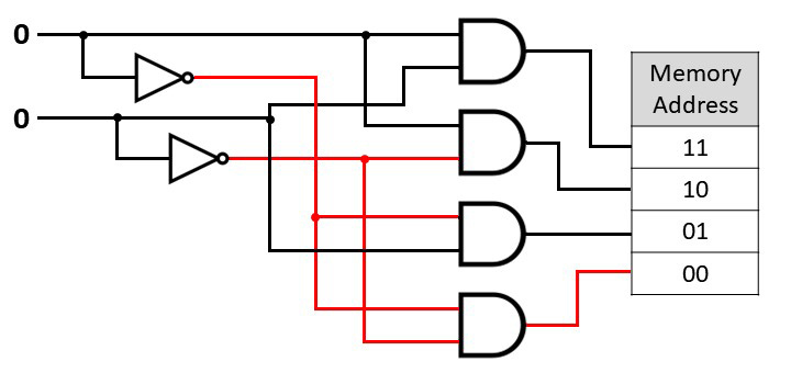
A decoder has n inputs and selects
one of 2n outputs. It can be used for selecting a
memory address. For example, if the memory address bus is 8-bits, then it
can address 256 different memory location. The decoder takes the 8-bit
binary digit and sends a signal along one of 256 different wires to select a
memory address. Below is a 2-bit decoder circuit.
|
2-Bit Decoder |
| |
|
 |
|
Click |
| |
|
Click |
|
|
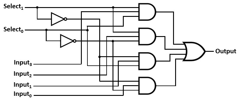
A multiplexer has multiple inputs and selects one
of them for the output. It is also known as a data selector.
An example would be selecting which data input goes to a communication line.