click pictures to enlarge
Below is a list of parts needed. Most parts can also be found on Amazon.
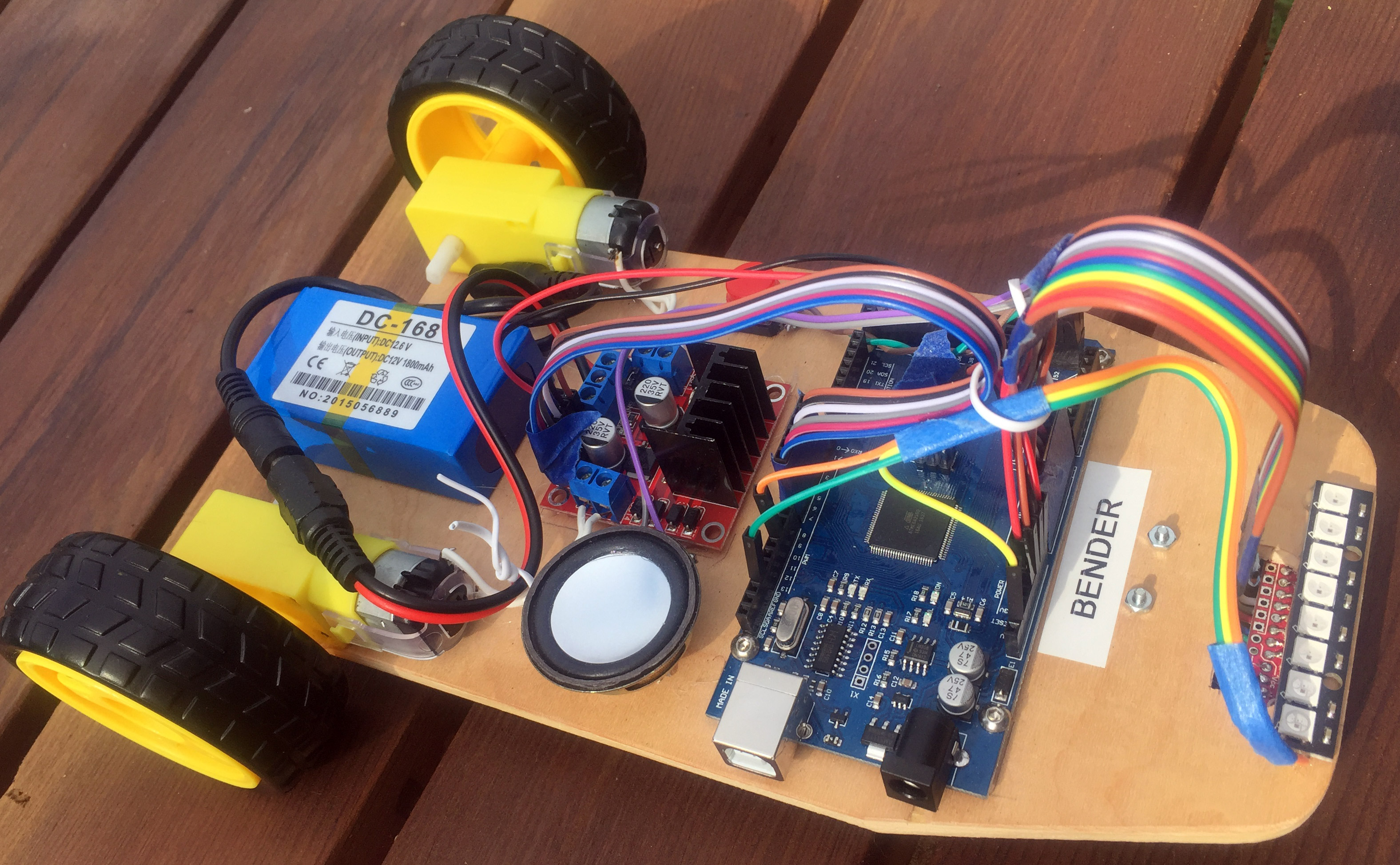
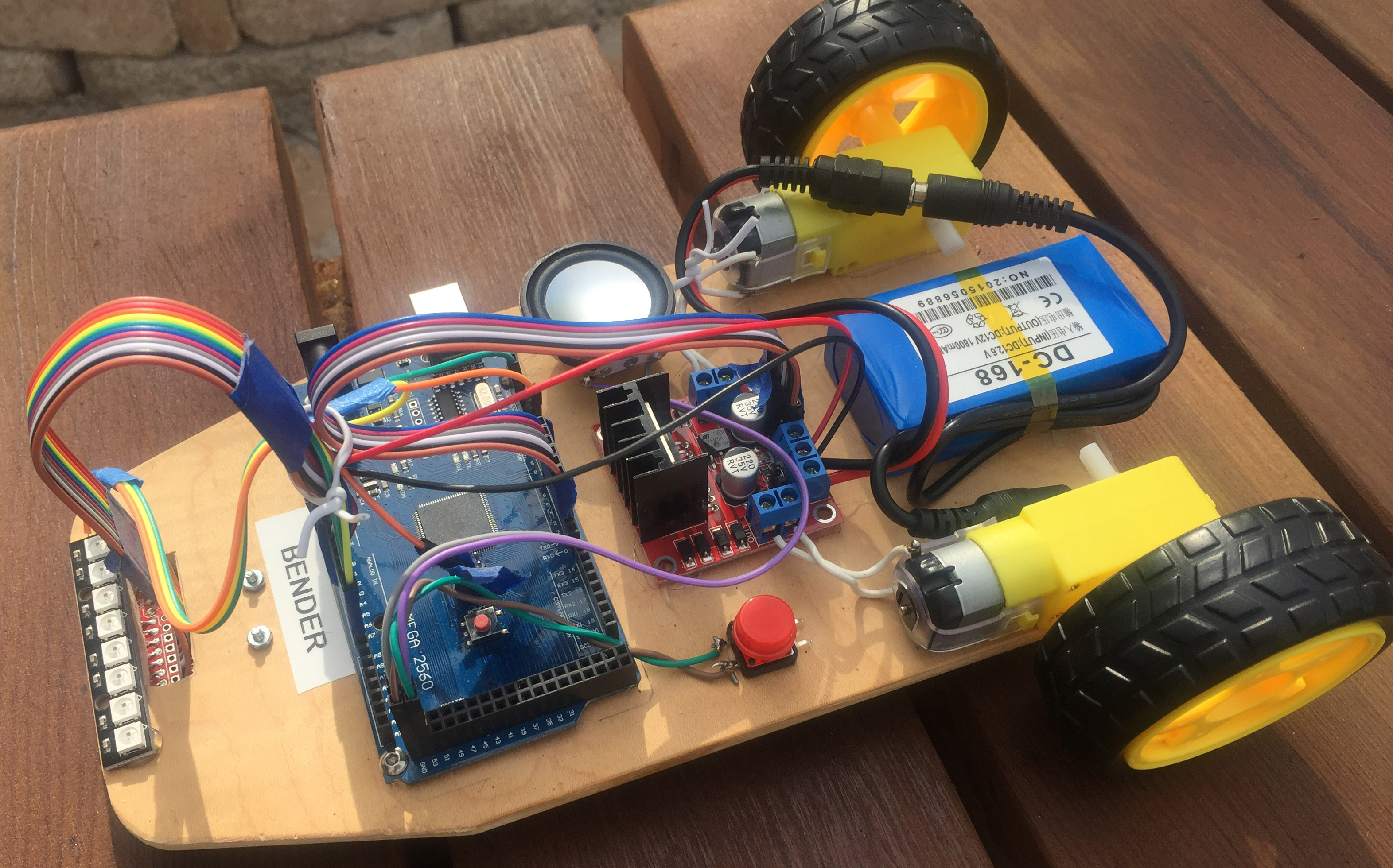
Build an Arduino Line
Following Robot
by David Kirk
Instructional YouTube Video:
https://youtu.be/vlrOqIcTcHc
click pictures to enlarge
Below is a list of parts needed. Most parts can also be found on Amazon.
| Item | Price | Supplier |
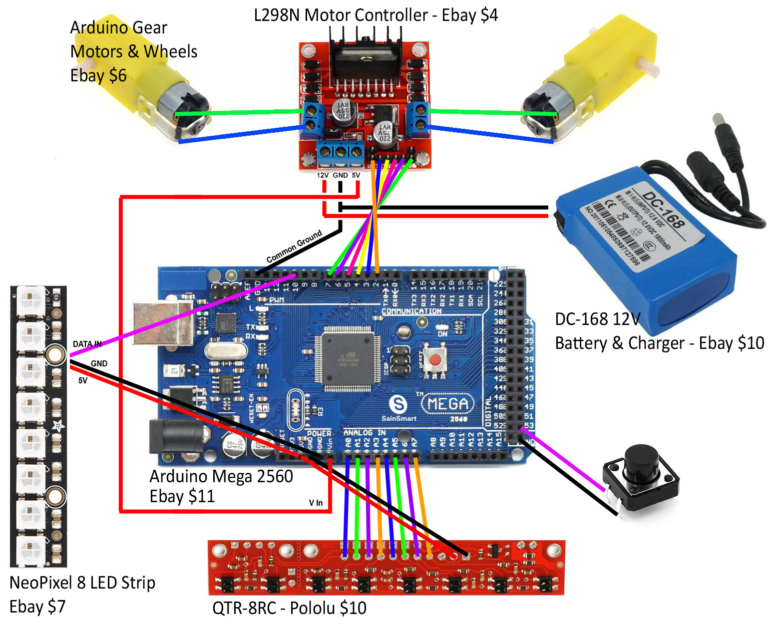
| Arduino Mega 2560 | $11 | Ebay |
| LN298 Motor Controller | $4 | Ebay |
| NeoPixel 8 LED Strip | $7 | Ebay |
| Dupont jumper wires (male to female) | $4 | Ebay |
| Arduino gear motors (wheels included) | $6 | Ebay |
| Arduino push button | $2 | Ebay |
| DC-168 12V battery & charger | $10 | Ebay |
| QTR-8RC | $10 | Pololu |
| Caster with 1/2" plastic ball | $2 | Pololu |
Notes
1. I like making the platform out of thin plywood. Acrylic can be
used but may crack easier.
2. Many parts can be hot glued to the platform. I recommend using
the supplied bolts for mounting the caster. The Arduino can be hot glued
but I attached mine with bolts since there's sideways pressure on it when you plug in
the data cable.
3. The floor needs to be a non-reflective surface such as dull carpet.
For the line, I'm using 1" red 3M duct tape that's shiny (reflective).
If you can find 2" then cut
it down the middle to have 1" width lines.
4. The threshold values will need to be changed depending on the floor,
reflective tape, and lighting.
5. If you use different motors such as ones from Pololu, make sure to get
one with a higher gear ratio (higher torque).
6. You can use an Arduino Uno, but can only connect 6 of the 8 sensors
on the QTR-8C - leave the middle two disconnected.
7. The QTR-8C will need to be soldered to the wires. Also, wires
need to be soldered to the motors and pushbutton.
Here's how to install the
QTRSensor library for Arduino.
8. The NeoPixel 8 LED Strip is not absolutely necessary, but definitely
helps so you can see what the sensors see.
Here's how to install the NeoPixel library.
8. I bought a female DC power connector to plug into the DC-168 battery,
however, you could cut the battery's 12v output wires (male connector) and plug
directly into the motor controller.
9. The robot in the pictures above also has a speaker to make beeps or to
play a victory song.
10. Check out another robot I built:
Kirk BB-8
|
Sample Line Following Robot Code |
|
// you made need to
install the old version (3.0) of QTRSensors.h library in Arduino IDE void Reverse (int
LeftSpeed, int RightSpeed) // range 0-255 |